
A split phase induction motor is a type of single-phase AC induction motor. It uses two windings: a main winding and an auxiliary winding to create the rotating magnetic field needed to start the motor. Without this starting arrangement, a single-phase motor cannot start on its own.
The name “split phase” comes from the fact that the single-phase supply is split into two phases that are slightly displaced from each other. This phase difference creates a rotating effect that produces the starting torque.
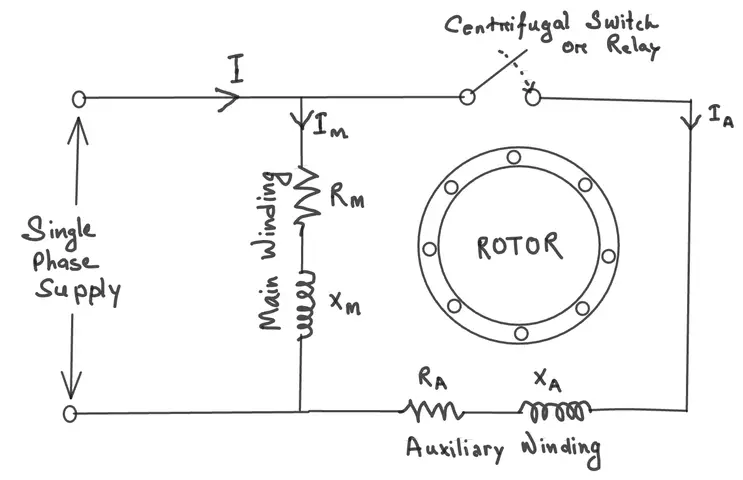
1. Why Does a Single-Phase Motor Need Help Starting?
A standard single-phase induction motor has a pulsating magnetic field, not a rotating one. A pulsating field cannot produce torque on its own. The rotor therefore simply sits there and vibrates.
To get the rotor moving, you need at least two phases that are displaced in time. The split phase method achieves this using two windings with different electrical characteristics. Once the motor picks up speed, the auxiliary winding is disconnected, and the motor continues to run on the main winding only.
2. Construction of a Split Phase Induction Motor
2.1 Stator
The stator has two separate windings placed 90 degrees apart:
Main Winding (Running Winding): This winding has a low resistance and high inductance. It is made of thick wire with many turns. This winding stays connected to the supply during both starting and running conditions.
Auxiliary Winding (Starting Winding): This winding has a high resistance and low inductance. It is made of thin wire with fewer turns. The high resistance gives it a different impedance from the main winding. This difference causes a phase shift between the two winding currents.
2.2 Rotor
The rotor used in split phase motors is a squirrel cage rotor. It has copper or aluminum bars short-circuited at both ends by end rings. There are no external connections to the rotor. It is rugged, simple, and maintenance-free.
2.3 Centrifugal Switch
A centrifugal switch is mounted on the rotor shaft. It stays closed during the starting phase of the motor. After starting, once the motor reaches around 75% to 80% of its synchronous speed, the switch opens and it disconnects the auxiliary winding from the supply.
This switch is placed in series with the auxiliary winding. If it fails to open, the starting winding gets overheated and may burn out very quickly as it is not designed for continuous operation.
3. Working Principle
When the motor is connected to the AC supply, both the main winding and the auxiliary winding receive current. The main winding current lags the supply voltage by a large angle due to its high inductance. The auxiliary winding current lags by a smaller angle due to its higher resistance.
This creates a time phase difference between the two currents of around 25-35 degrees. These two currents flowing through spatially displaced windings produce a rotating magnetic field. The field rotates and induces a current in the squirrel cage rotor. This induced current interacts with the rotating field to produce torque, and the rotor starts to move.
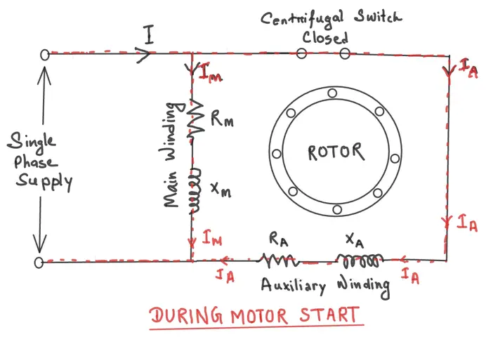
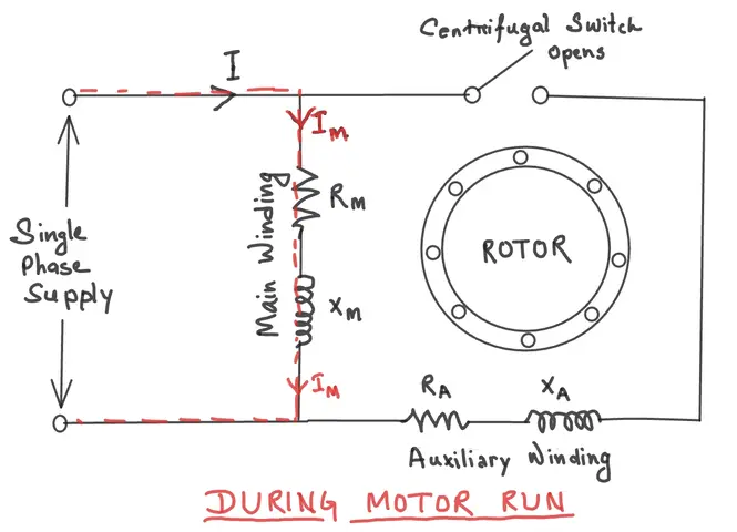
As the rotor accelerates, the centrifugal switch opens at around 75%-80% of synchronous speed and the auxiliary winding gets disconnected. The motor then runs on the main winding only, and it continues to operate because the rotor has enough momentum to maintain its rotation.
4. Phasor Diagram Explanation
In the phasor diagram of a split phase motor:
- The supply voltage \(V\) is taken as the reference phasor.
- The main winding current \(I_m\) lags \(V\) by a large angle \(phi_m\) of around 40°–50°.
- The auxiliary winding current \(I_a\) lags \(V\) by a smaller angle \(phi_a\) of around 10°–15°.
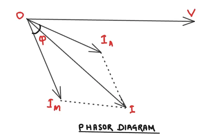
The angle \(\phi\) between \(I_m\) and \(I_a\) is the phase difference between the two currents. For better starting torque, this angle should be as large as possible and it should ideally be 90 degrees. But in a standard practical split phase motor, this angle is only around 25-35 degrees, which is why the starting torque is low.
5. Torque-Speed Characteristics
The split phase induction motor has these torque characteristics:
- Starting Torque: Low — around 150% to 200% of full-load torque. This is one of the limitations of this motor type.
- Breakdown Torque: Moderate.
- Running: After the auxiliary winding disconnects, the motor runs on the main winding and behaves like a standard single-phase induction motor.
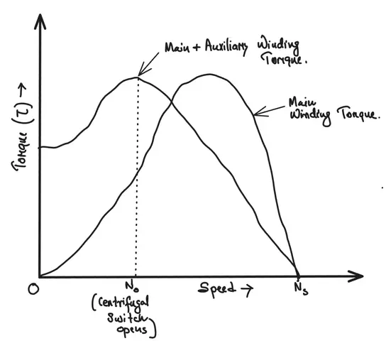
This motor is not suited for applications that need high starting torque. It works best for loads that start easily, like fans, blowers, and washing machines.
6. Advantages of Split Phase Induction Motor
- Simple construction with no brushes or slip rings
- Low cost compared to other single-phase motor types
- Reliable and easy to maintain
- Squirrel cage rotor needs almost no maintenance
- Directly connected to standard single-phase AC supply
7. Disadvantages of Split Phase Induction Motor
- Low starting torque — not suitable for high-load starting applications
- The auxiliary winding can burn out if the centrifugal switch fails
- The phase difference between the two windings is small (around 30°), which limits starting performance
- Not suitable for heavy-duty or frequent start-stop operations
- Starting current is relatively high compared to the starting torque produced
8. Applications of Split Phase Induction Motor
Here are the common applications:
- Washing machines
- Fans and blowers
- Centrifugal pumps (lightly loaded at start)
- Small grinding machines
- Drilling machines (small capacity)
- Air conditioning unit fans
- Office equipment like photocopiers
All these loads have one thing in common — they do not require heavy torque at the moment of starting. The split phase motor is adequate for these situations.
9. Comparison With Capacitor-Start Motor
The capacitor-start motor uses a capacitor in series with the auxiliary winding. This shifts the auxiliary winding current by nearly 90 degrees from the main winding current. This gives stronger starting torque compared to Split Phase motor.
| Feature | Split Phase Motor | Capacitor-Start Motor |
|---|---|---|
| Starting Torque | Low (150%-200% FLT) | High (300%-450% FLT) |
| Phase Difference | ~30° | ~80°-90° |
| Auxiliary Winding | Resistive | Capacitor in series |
| Cost | Lower | Slightly higher |
| Application | Light loads | Heavy starting loads |
10. How to Reverse the Direction of a Split Phase Motor
To reverse the rotation of a split phase induction motor, reverse the connections of either the main winding or the auxiliary winding — but not both. Reversing only one winding reverses the direction of the rotating magnetic field, which reverses the rotor direction.
Do not reverse the power supply terminals. That will not change the direction of rotation. You need to swap the terminals of one of the two windings.
11. Conclusion
The split phase induction motor is a simple and economical solution for low starting torque applications. It works by splitting the single-phase supply into two phases using two windings with different impedance characteristics. The centrifugal switch disconnects the auxiliary winding after startup, and the motor continues running on the main winding.
This motor is best suited for light-duty applications where the load is minimal at the time of starting. For applications requiring high starting torque, a capacitor-start or capacitor-start-capacitor-run motor would be a better choice.
12. Frequently Asked Questions (FAQs)
The centrifugal switch disconnects the auxiliary winding from the supply once the motor reaches around 75%-80% of its synchronous speed. The auxiliary winding is only needed for starting. Keeping it energized during running would cause it to overheat and burn out.
The phase difference between the main winding current and the auxiliary winding current is only about 30 degrees. For maximum torque, this angle should be 90 degrees. Since split phase motors only achieve around 30 degrees, the starting torque remains relatively low.
No. A split phase induction motor is specifically designed for single-phase AC supply. Connecting it to a three-phase supply will damage the motor and is not a safe practice.
If the centrifugal switch stays closed, the auxiliary winding remains connected to the supply during the running condition. Since the auxiliary winding is made of thin wire and has high resistance, it is not built for continuous operation. It will overheat rapidly and burn out.
Interchange the terminals of either the main winding or the auxiliary winding — not both. This reverses the direction of the rotating magnetic field and, in turn, reverses the direction of rotor rotation.