
A half wave rectifier is a circuit that converts alternating current (AC) into direct current (DC). It allows only one half of the AC waveform to pass through it and completely blocks the other half of the waveform.
The output of a half wave rectifier is a pulsating DC signal which is not smooth. The output has the same frequency as the input if the positive half cycles are counted.
This circuit of a half wave rectifier uses a single diode as the main component. The diode acts like a one-way valve for current. Current flows in one direction and gets blocked in the other direction.
1. Basic Circuit Diagram
The half wave rectifier circuit has three main parts:
- A transformer (step-down or step-up)
- A single PN junction diode
- A load resistor \((R_L)\)
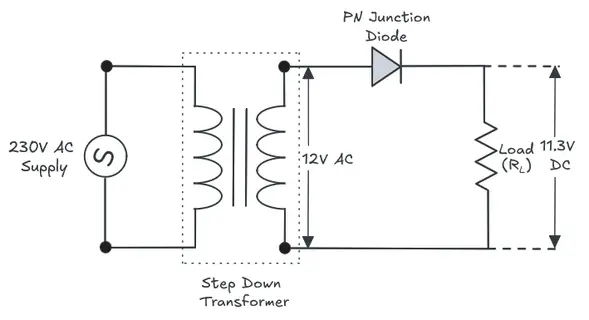
The AC input supply is connected to the primary winding of the transformer and the secondary winding of the transformer provides the required AC voltage. This secondary AC voltage is then applied across the series combination of the PN junction diode and the load resistor as shown in the figure above.
The output voltage of a half wave rectifier is measured across the load resistor.
2. How Does a Half Wave Rectifier Work?
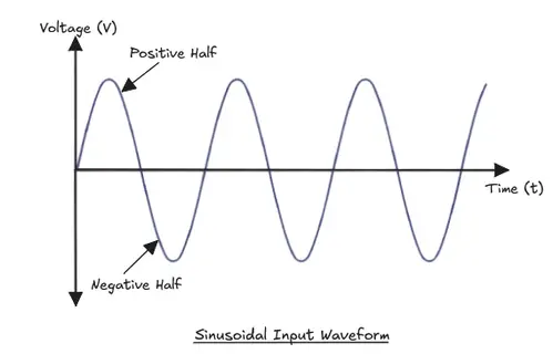
During the Positive Half Cycle of AC waveform, the AC input goes positive. The anode of the diode becomes more positive than the cathode. This forward biases the diode and current flows through the diode and through the load resistor. A positive voltage appears across the load.
During the Negative Half Cycle of AC waveform, the AC input goes negative. The anode becomes more negative than the cathode. This reverse biases the diode and the diode blocks current. No current flows through the load. The output voltage is zero during the negative half cycle of the waveform.
So the output of half wave rectifier consists of only the positive half cycles of the input AC waveform. The negative half cycles are completely removed as shown in the figure below.
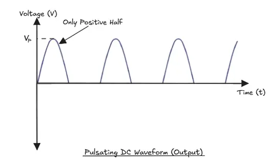
If the diode is flipped in the circuit, the output will show only the negative half cycles. Therefore, the direction of the diode in the circuit determines which half cycle appears at the output.
The output waveform looks like a series of humps. Each hump represents one positive half cycle of the input or one negative half cycle of input depending upon the direction of the diode. Between two consecutive humps, the output is flat and zero. These flat regions represent the time when the diode is reverse biased.
This output is called pulsating DC because it never goes negative. But it is not steady and rises and falls with each cycle.
3. Mathematical Formulas of Half Wave Rectifier
3.1 Peak Voltage
If the RMS voltage of the AC input waveform is \(V_{rms}\), then the peak voltage is given by:
\(V_{peak} = V_{rms} \times \sqrt{2}\)
For example, if the transformer secondary gives 12V RMS, the peak voltage is:
\(V_{peak} = 12 \times \sqrt{2} = 16.97 \text{ V}\)
In practice, the diode forward voltage drop is subtracted (approximately 0.7V for silicon diodes):
\(V_{peak(output)} = V_{peak(input)} − 0.7 \text{ V}\)
\(V_{peak(output)} = 16.97 − 0.7 V = 16.27 \text{ V}\)
3.2 Average (DC) Output Voltage
The average voltage over a full cycle is calculated by integrating the sine wave over one full period. Since the output is zero for half the cycle:
\(V_{avg} = \dfrac{V_{peak}}{\pi}\)
Or approximately:
\(V_{avg} = 0.318 \times V_{peak}\)
The average output voltage \(V_{avg}\) appears at DC voltmeter when connected across the load.
3.3 RMS Output Voltage
\(V_{rms(output)} = \dfrac{V_{peak}}{2}\)
Or:
\(V_{rms(output)} = 0.5 \times V_{peak}\)
3.4 Peak Inverse Voltage (PIV)
Peak inverse voltage is the maximum reverse voltage that appears across the diode during the negative half cycle when the diode is reverse biased. For a half wave rectifier with no filter the peak inverse voltage is given by:
\(PIV = V_{peak}\)
The diode must be rated to withstand peak inverse voltage. If the PIV rating of the diode is lower than this value, the diode will break down during the negative half cycle of the waveform.
3.5 Ripple Factor
Ripple factor is the measurement AC component is present in the output waveform. A lower ripple factor means a cleaner DC output.
\(\text{Ripple factor} (\gamma) = \sqrt{\left(\dfrac{V_{rms}}{V_{avg}}\right)^2 − 1}\)
For an ideal half wave rectifier:
\(\gamma = 1.21\)
This is a very high value and it means that the output waveform has a lot of ripple and has more AC noise than DC.
3.6 Rectifier Efficiency
Rectifier efficiency is defined as the percentage of the input AC power that is converted to useful DC output power.
\(\text{Efficiency} (\eta) = \left(\dfrac{P_{dc}}{P_{ac}}\right) \times 100\)
For an ideal half wave rectifier the efficiency is:
\(\eta = 40.6\%\)
In practice, the efficiency is lower than this value due to the forward resistance of the diode and transformer losses.
3.7 Form Factor
Form factor is the ratio of RMS output voltage to average output voltage.
\(\text{Form Factor} = \dfrac{V_{rms}}{V_{avg}} = \dfrac{\left(\frac{V_{peak}}{2}\right)}{\left(\frac{V_{peak}}{\pi}\right)} = \dfrac{\pi}{2} \approx 1.57\)
3.8 Transformer Utilization Factor (TUF)
TUF indicates how well the transformer is being used.
\(\text{TUF} = \dfrac{P_{dc}}{\text{VA rating of transformer}}\)
For a half wave rectifier:
\(\text{TUF} = 0.287\)
This is very low and indicates that the transformer is not being used efficiently because it only delivers power for half the cycle.
4. Half Wave Rectifier With Filter Capacitor
As discussed above. the raw output of a half wave rectifier has a lot of ripple. A filter capacitor placed across the load resistor as shown in the figure below smooths out the output waveform.
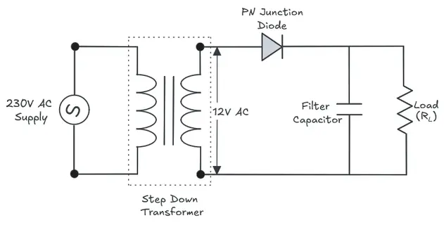
During the positive half cycle of the input waveform, the diode conducts and current flows through the load. At the same time, the capacitor charges up to the peak voltage.
During the negative half cycle, the diode is reverse biased. The capacitor starts discharging through the load resistor. It supplies current to the load while the diode is off.
When the capacitor value is large, the discharge process becomes slow and the output voltage drops very less before the next positive peak arrives. This reduces the ripple in the output.
The remaining ripple voltage after filtering is:
\(V_{ripple} \approx \dfrac{V_{peak}}{(f \times R_L \times C)}\)
Where:
- \(f\) = frequency of the supply (50 or 60 Hz)
- \(R_L\) = load resistance
- \(C\) = capacitance value
For example, if
\(V_{peak} = 10V\),
\(f = 50 Hz\),
\(R_L = 1000 Ω\), and
\(C = 1000 µF\)
\(V_{ripple} = \dfrac{10}{(50 \times 1000 \times 0.001)} = \dfrac{10}{50} = 0.2 V\)
This shows that the filtered output is cleaner and has very less ripple compared to the non filtered output.
Note: When filter capacitor is added, the PIV across the diode increases. In the worst case, it can reach up to 2 × V_peak. The diode PIV rating must be higher to handle the increase in PIV.
5. Practical Example: Designing a Half Wave Rectifier
Let’s say you need a DC output of approximately 9V DC to power a small circuit. Here is how you would design a basic half wave rectifier.
Step 1: Find the required \(V_{avg}\)
You need \(V_{avg} = 9V\).
Since \(V_{avg} = \dfrac{V_{peak}}{\pi}\):
\(V_{peak} = V_{avg} \times \pi = 9 \times 3.14 = 28.3V\)
Step 2: Find the transformer secondary voltage
\(V_{peak} = V_{rms} \times \sqrt{2}\)
\(V_{rms} = \dfrac{V_{peak}}{\sqrt{2}} = \dfrac{28.3}{1.414} = 20 V \text{RMS}\)
So you need a transformer with a secondary output of 20V RMS. A 24 volt secondary transformer is best for this purpose considering the 0.7V diode drop and transformer regulation.
Step 3: Choose the diode
\(\text{PIV} = V_{peak} = 28.3 V\).
Choose a diode rated for at least 50V PIV to have a safe margin. A 1N4007 (rated for 1000V PIV, 1A) works perfectly for low-current loads.
Step 4: Add a filter capacitor
For a load of 100 mA at 9V, \(R_L = \dfrac{9}{0.1} = 90 \Omega\)
\(V_{ripple} \approx \dfrac{V_{peak}}{(f \times R_L \times C)}\)
For a 1V ripple at 50 Hz:
\(C = \dfrac{V_{peak}}{(f \times R_L \times V_{ripple})} = \dfrac{28.3}{(50 \times 90 \times 1)} = 6.3 mF\)
A 6800 µF or 10000 µF electrolytic capacitor can be used for the purpose.
6. Advantages of Half Wave Rectifier
- The circuit is simple and only one diode is needed.
- It is cheap to build.
- Less components means less space on the PCB.
- Easy to troubleshoot.
7. Disadvantages of Half Wave Rectifier
- Efficiency is only 40.6%. More than half the input power is wasted.
- The ripple factor 1.21 is very high. The output has a lot of AC content.
- The transformer is used inefficiently (TUF = 0.287). The secondary winding carries DC current, which causes extra heating and core saturation issues.
- The output frequency is the same as the input frequency. This makes filtering harder compared to a full wave rectifier.
- Not suitable for high-power applications.
8. Applications of Half Wave Rectifier
Even if half wave rectifier circuit has several limitations, it is used in several practical applications.
Battery Charging Circuits: Simple chargers for small batteries use half wave rectifiers. The pulsating DC is still sufficient to charge a battery. A small resistor and the battery itself act as a filter.
Signal Demodulation: In AM radio receivers, a diode is used to detect the audio signal from the modulated carrier. This is half wave rectification applied to high-frequency signals.
Power Supplies for Low-Current Loads: Some small electronic devices like indicator lights or low-power signal circuits do not need perfectly smooth DC. A half wave rectifier with a capacitor used for these loads.
Voltage Multiplier Circuits: Half wave rectifiers form the building blocks of voltage doubler and multiplier circuits used in cathode ray tubes (CRTs), X-ray machines, and some other test equipment.
Firing Circuits for SCR/Thyristor: Some thyristor triggering circuits use half wave rectification to generate the gate pulses needed at the right phase angle.
9. Conclusion
The half wave rectifier is the simplest rectifier circuit built with just one diode. It converts AC to pulsating DC by passing only one half of the input waveform. The average output voltage of a half wave rectifier is \(0.318 \times V_{peak}\), efficiency is 40.6%, and ripple factor is 1.21. These numbers clearly shows the limitations of a half wave rectifier.
However, a filter capacitor improves the output a little bit but does not fix the core inefficiencies. A half wave rectifier is generally used for low-power, low-cost applications like battery chargers and signal detectors. For higher efficiency and cleaner DC output, a full wave rectifier is the better choice.
10. Frequently Asked Questions (FAQs)
The output frequency is the same as the input AC frequency. If the input is 50 Hz, the output pulsates at 50 Hz.
The circuit only uses one half of the AC input. The other half is blocked by the diode. So effectively, only 50% of the input waveform contributes to the output, and after accounting for the losses in the diode and transformer, the net efficiency comes out to about 40.6%.
PIV stands for Peak Inverse Voltage. It is the maximum reverse voltage that the diode has to block during the negative half cycle. If the PIV of the diode is lower than the applied reverse voltage, the diode will break down and fail.
Yes, it can. You can connect a diode directly between the AC supply and the load. But this is dangerous at mains voltage levels. There is no electrical isolation from the supply. Any fault can expose the user or connected equipment to full mains voltage.
Ripple factor measures how much AC content remains in the DC output. A ripple factor of 1.21 means the AC ripple component in the output is 121% of the DC component.
The negative half cycles will appear at the output instead of the positive half cycles. The circuit still rectifies and it is still a half wave rectifier but the output polarity is reversed.
No. Both circuits use diodes, and both remove part of the waveform. But the purpose is different. A clipper circuit clips part of a signal for waveform shaping purposes, and it usually passes the result to another signal-processing stage. A rectifier converts AC power into DC power for supplying a load.