
Resistance is defined as the opposition that a material offers to the flow of electric current. Think of it like friction. Just like friction slows down a moving object, resistance slows down the movement of electrons in a conductor.
Every material has some electrical resistance. For example, copper has very low resistance and rubber has very high resistance.
The unit of resistance is the Ohm, represented by the Greek letter Ω (Omega). It was named after the German physicist Georg Simon Ohm.
1. The Physics Behind Resistance
At the atomic level, electric current is the movement of free electrons through a conducting material as shown in the figure below. These free electrons do not travel in a straight, uninterrupted path and they constantly collide with the atoms and other electrons that make up the material’s structure. Each collision slows down the electrons and redirects their movement. This continuous interruption in the movement of electrons produces electrical resistance.
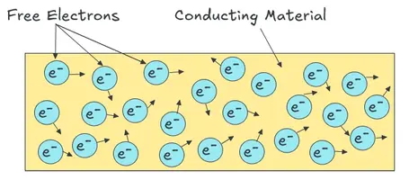
Metals like copper have a loosely bound outer electron shell and this allows electrons to move freely between atoms. Materials like rubber or glass hold their electrons tightly and leaves no free electrons available to move freely. Therefore, rubber is a strong insulator and copper is a good conductor.
The resistance of a conducting materials directly depends upon the length and cross section area of the material. A longer wire gives electrons a greater distance to travel. This means more collisions and higher resistance.
However, a thicker wire gives electrons more cross-sectional space to move. This reduces the number of collisions per unit area and lowers the resistance of the material.
2. Formula for Resistance
The resistance of a conductor can be calculated using the formula:
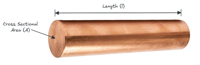
\(R = \rho \times \dfrac{L}{A}\)
Where:
- \(R\) = Resistance in Ohms (Ω)
- \(\rho\) (rho) = Resistivity of the material (in Ω·m)
- \(L\) = Length of the conductor (in meters)
- \(A\) = Cross-sectional area (in square meters)
Practical Example
Suppose you have a copper wire with a length of 10 meters and a cross-sectional area of \(1 \times 10^{-6} \,m^2\). The resistivity of copper is approximately \(1.68 \times 10^{-8}\) Ω·m.
\(R = 1.68 \times 10^{-8} \times \dfrac{10}{1 \times 10^{-6}}\)
\(R = 1.68 \times 10^{-8} \times 10^7\)
\(R = 0.168 \Omega\)
3. Ohm’s Law
Ohm’s Law is the most used relationship in circuit analysis that connects voltage, current, and resistance in one equation provided below:
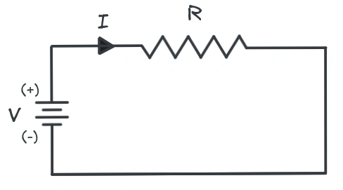
\(V = I \times R\)
Where:
- \(V\) = Voltage in Volts (V)
- \(I\) = Current in Amperes (A)
- \(R\) = Resistance in Ohms (Ω)
Practical Example
A 9V battery is connected to a resistor. The current measured is 0.03 A (30 mA). What is the resistance?
\(R = \dfrac{V}{I}\)
\(R = \dfrac{9}{0.03}\)
\(R = 300 Ω\)
4. Resistivity vs. Resistance
Resistivity and resistance of a material are related to each other, but they are not the same and should not be used interchangeably.
Resistivity is a property of the material itself. It tells how strongly a given material opposes the flow of current regardless of the shape or size of the material.
If you take two copper wires of different lengths and thicknesses, both will have the same resistivity value as they are made of the same material. Resistivity is denoted by the Greek letter \(\rho\) (rho) and is measured in Ohm-meters \((\Omega . m)\).
On the other hand, resistance depends on both the material and its physical dimensions. A thin, long wire will have higher resistance than a short, thick wire made from the same material.
In simple terms, resistivity is the material’s natural tendency to oppose current and resistance is the actual opposition measured in a specific piece of that material with specific dimensions.
Resistivity values for common materials are provided in the list below:
| Material | Resistivity (Ω·m) at 20°C |
|---|---|
| Silver | 1.59 × 10⁻⁸ |
| Copper | 1.68 × 10⁻⁸ |
| Aluminum | 2.82 × 10⁻⁸ |
| Tungsten | 5.60 × 10⁻⁸ |
| Iron | 1.00 × 10⁻⁷ |
| Carbon | 3.5 × 10⁻⁵ |
| Silicon | 6.40 × 10² |
| Glass | 10¹⁰ to 10¹⁴ |
| Rubber | 10¹³ |
5. Types of Resistors
A resistor is a passive component designed to introduce a specific amount of resistance into a circuit. There are many types of resistors used.
5.1 Fixed Resistors
As the name suggests, fixed resistors have a set resistance value that does not change. They are the most common type of resistors used in circuits. Carbon film, metal film, and wire-wound resistors fall into this category.
- Carbon film resistors are inexpensive and used in general-purpose circuits.
- Metal film resistors offer better precision and stability.
- Wire-wound resistors handle high power loads. They are made by winding a resistive wire around a ceramic core.
5.2 Variable Resistors
The type of resistors that allows to adjust the resistance value manually are called the variable resistors.
A potentiometer is an example of a variable resistor. It has three terminals and is used in volume controls, position sensors, and calibration circuits.
A rheostat is another type of variable resistor. It has only two terminals and is used for controlling current in lamp dimmers, motor speed controllers, etc.
5.3 Thermistors (Temperature-Dependent Resistors)
A thermistor is a device that changes its resistance according to temperature. There are two types of thermistors:
NTC (Negative Temperature Coefficient) thermistors decrease in resistance as temperature goes up. They are used in temperature sensing and inrush current protection.
PTC (Positive Temperature Coefficient) thermistors increase in resistance as temperature rises. They are used as self-resetting fuses.
5.4 LDR (Light Dependent Resistors)
An LDR changes its resistance value based on the intensity of light. In bright light, the resistance drops and in darkness, the resistance increases. These type of resistors are used in automatic street lights and camera exposure control.
5.5 Varistors (Voltage-Dependent Resistors)
A varistor or voltage-dependent resistor changes resistance based on the applied voltage. At normal voltage levels, the resistance is very high and does not allow current to pass through it. At high voltage spikes, resistance drops very sharply and diverts the excess current. They are used for surge protection in power supplies and home appliances.
6. Power Dissipation in Resistors
Resistors convert electrical energy into heat. This is called power dissipation. The power dissipated by a resistor can be calculated using the following formula.
\(P = I^2 \times R\)
Or equivalently:
\(P = \dfrac{V^2}{R}\)
Or:
\(P = V \times I\)
Practical Example
A 470 Ω resistor carries a current of 20 mA (0.02 A).
\(P = I^2 \times R = (0.02)^2 \times 470 = 0.0004 \times 470 = 0.188 W\)
This means the resistor dissipates about 188 mW of power.
7. Effect of Temperature on Resistance
For most metals, resistance increases with temperature. This relationship is described by:
\(R_T = R_0 \times [1 + \alpha(T – T_0)]\)
Where:
- \(R_T\) = Resistance at temperature T
- \(R_0\) = Resistance at reference temperature T₀ (usually 20°C)
- \(\alpha\) = Temperature coefficient of resistance (in 1/°C)
- \(T\) = New temperature
Example
A copper wire has a resistance of 10 Ω at 20°C. The temperature coefficient of copper is 0.00393 /°C. What is the resistance at 80°C?
\(R_T = 10 × [1 + 0.00393 × (80 – 20)]\)
\(R_T = 10 × [1 + 0.00393 × 60]\)
\(R_T = 10 × [1 + 0.2358]\)
\(R_T = 10 × 1.2358 = 12.36 Ω\)
The resistance increased by about 23.6% due to the temperature rise.
8. Conclusion
Resistance is the opposition to electric current flow in a conductor, measured in Ohms (Ω). It depends on material resistivity, conductor length, cross-sectional area, and temperature. Every practical circuit design involves resistance at some level.
9. Frequently Asked Questions (FAQs)
Resistance is the opposition offered by a material to the flow of electric current. It is measured in Ohms (Ω).
Resistance in a wire is caused by collisions between moving electrons and the atoms inside the material. These collisions slow down the electron flow.
For metals as the temperature increases, atoms vibrate more intensely, causing more collisions with electrons, which increases resistance. However, for semiconductors, resistance decreases with temperature.
Resistivity is a property of the material itself and does not depend on shape or size. Resistance depends on both the material and its physical dimensions.
In normal conductors at room temperature, resistance cannot be zero. However, in superconductors at extremely low temperatures, resistance drops to zero.
If the length is doubled and all other factors remain the same, the resistance also doubles.
Adding resistors in parallel creates additional current paths. More paths mean current can flow more easily, which reduces the overall opposition to current flow, giving a lower total resistance.