
Transformer parallel operation is the practice of connecting two or more transformers such that their primary windings share a common source and their secondary windings feed a common load bus. This arrangement is widely used in power distribution systems, industrial plants, data centers, and high-demand commercial facilities.
There are many reasons engineers choose to operate transformers in parallel. The most common reason is that the load demand at a substation or facility has grown beyond the capacity of a single transformer. Instead of replacing that transformer with a larger one, a second unit can be connected in parallel.
Parallel transformer operation also provides redundancy. If one transformer trips due to a fault, the remaining unit continues supplying the load. This makes the system more reliable, especially in applications where continuous power supply is non-negotiable, such as hospitals, airports, and industrial production lines.
However, connecting transformers in parallel is not as simple as just wiring two units together. Specific technical conditions must be satisfied for the arrangement to work correctly and safely.
In this technical guide, we will discuss everything you need to know about transformer parallel operation, including its working principle, conditions, load sharing formulas, circulating currents, vector group compatibility, protection methods, practical examples, and relevant industry standards. Practical examples are included throughout to help you apply these concepts in real-world scenarios confidently.
1. What Is Transformer Parallel Operation?
Transformer parallel operation means connecting the primary terminals of two or more transformers to the same source bus and connecting their secondary terminals to the same load bus. The transformers then share the load current flowing from the source to the load.
Think of it like connecting two water pumps to the same pipeline. Each pump contributes to the total water flow, and together they can supply more than either one could alone. The same idea applies to parallel transformers supplying a common electrical load.
In a substation setup, two 1000 kVA transformers can be connected in parallel to supply a load of up to 2000 kVA. If the load is only 800 kVA under normal conditions, one transformer carries the load. During peak hours when demand rises, the second transformer is switched in to share the load.
A simple representation of parallel transformer connection in a three-phase system looks like this:
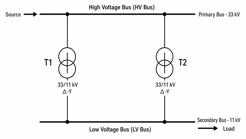
This arrangement is fundamental to modern power systems. Without the ability to parallelize transformers, substation design would be far more rigid and expensive.
2. Why Operate Transformers in Parallel?
There are several practical and economic reasons why engineers connect transformers in parallel.
2.1 Capacity Expansion Without Full Replacement
The most common reason for parallel operation is load growth. When a distribution substation was originally designed, it may have been equipped with a single 2 MVA transformer. Over time, load demand in the area grows to 3.5 MVA. Rather than replacing the 2 MVA unit with a 4 MVA unit, a second transformer of 1.5 MVA or 2 MVA rating can be added in parallel.
2.2 Supply Continuity and Redundancy
Operating two transformers in parallel means the system can still supply the load if one transformer goes offline for maintenance or due to a fault. For example, a hospital that cannot afford even a short power interruption will operate two parallel transformers so that losing one does not cause a complete outage.
2.3 Flexibility in Load Management
Parallel operation allows operators to switch transformers in and out based on load demand. During off-peak hours, one transformer can be de-energized to reduce no-load losses. During peak hours, both units are brought online to meet demand. This flexible approach improves overall energy efficiency.
2.4 Transportation and Installation Constraints
Very large transformers are difficult to transport and install. In some locations, roads, bridges, or facility access constraints make it impossible to bring in a single large transformer. In such cases, two smaller units are transported and installed in parallel to achieve the required capacity.
3. Conditions for Transformer Parallel Operation
This is the most important part of transformer parallel operation. If these conditions are not met, the transformers will not share load properly or, worse, dangerous circulating currents will flow even without any external load connected.
There are five main conditions that must be satisfied for successful parallel operation.
3.1 Condition 1 — Same Voltage Ratio (Turn Ratio)
Both transformers must have the same voltage ratio. That means if Transformer T1 steps down from 11 kV to 415 V, then Transformer T2 must also step down from 11 kV to 415 V.
If the voltage ratios are not equal, the secondary voltages of the two transformers will be different. Even without any load connected, a voltage difference will exist between the two secondary windings. This voltage difference will drive a circulating current through the closed loop formed by the two secondary windings.
This circulating current has no useful purpose. It heats up the windings, wastes energy, and can damage the transformers over time.
3.1.1 Practical Example
Suppose T1 has a turns ratio of 11000/415 V and T2 has a turns ratio of 11000/420 V. The voltage difference is 420 − 415 = 5 V. This 5 V acts across the combined impedance of both transformers.
\(\text{Circulating Current} (I_C) = \dfrac{\Delta V}{Z_1+Z_2}\)
Where \(\Delta V\) is the voltage difference and \(Z_1\), \(Z_2\) are the impedances of T1 and T2 referred to the secondary side.
Even a small difference in voltage ratio can produce a large circulating current if the transformer impedances are low.
3.2 Condition 2 — Same Polarity
For single-phase transformers, the polarity must be the same. For three-phase transformers, the terminals must be connected with matching polarity so that the secondary voltages add up correctly in the parallel circuit.
If polarity is reversed, the two secondary voltages will be in phase opposition. Instead of a small circulating current due to a small voltage difference, there will be a large circulating current due to the sum of the two secondary voltages driving current around the loop. This can be roughly twice the full-load voltage driving current through very low impedance, resulting in an extremely high current that will trip protection or damage the transformers.
3.2.1 How Polarity Is Marked
In practice, transformer terminal polarity is marked using dot notation or H1, H2, X1, X2 labeling per ANSI/IEEE standards:
ANSI Terminal Marking for Single-Phase Transformers:
Primary: H1 (+), H2 (−)
Secondary: X1 (+), X2 (−)
For parallel connection, H1 of T1 connects to H1 of T2, and X1 of T1 connects to X1 of T2.
3.3 Condition 3 — Same Per-Unit Impedance (or Percentage Impedance)
Both transformers should have the same per-unit impedance. This condition directly affects how the load is shared between the two transformers.
If both transformers have the same per-unit impedance, they share the load in proportion to their kVA ratings. If the per-unit impedances are different, the transformer with the lower impedance will carry more load than its fair share based on rating. This can lead to one transformer being overloaded while the other is underloaded.
Practical Example:
T1 is rated 1000 kVA with 5% impedance.
T2 is rated 1000 kVA with 4% impedance.
Even though both transformers have the same kVA rating, T2 will carry more load because it offers less opposition to current flow. If the total load is 2000 kVA, T2 will carry more than 1000 kVA and may be overloaded.
The general rule is that the per-unit impedances of the two transformers should be equal or at least within a ratio of 0.9 to 1.1. Going beyond this range will result in poor load sharing.
3.4 Condition 4 — Same Phase Sequence (Three-Phase Transformers)
For three-phase transformers, the phase sequence of both transformers must be the same. Phase sequence is the order in which the three phases reach their peak voltages — either A-B-C (positive sequence) or A-C-B (negative sequence).
If two transformers with different phase sequences are connected in parallel, the secondary voltages will be displaced by 120 degrees relative to each other. This will result in very large circulating currents that will immediately damage the transformers or trip the protection system.
Phase sequence is checked using a phase sequence meter or a phase sequence indicator before making the parallel connection.
3.5 Condition 5 — Same Vector Group (Phase Displacement)
This condition applies to three-phase transformers. The vector group describes the winding connection (Delta or Star) and the phase displacement between the primary and secondary voltages.
For example, a transformer with vector group Dyn11 has a 30-degree phase shift between its primary and secondary voltages. A transformer with vector group Yyn0 has zero phase shift.
If a Dyn11 transformer is connected in parallel with a Yyn0 transformer, there will be a 30-degree phase difference between their secondary voltages. Even if the voltage magnitudes are equal, this 30-degree difference will cause a large circulating current that can be as high as 86% of the short-circuit current.
3.5.1 Compatible Vector Groups
Transformers can only be operated in parallel if they belong to the same group in the following classification:
- Group 1 (0-degree phase shift): Yy0, Dd0, Dz0
- Group 2 (180-degree phase shift): Yy6, Dd6, Dz6
- Group 3 (−30-degree phase shift): Dy1, Yd1, Yz1
- Group 4 (+30-degree phase shift): Dy11, Yd11, Yz11
Transformers from Group 1 can be paralleled with Group 2. Transformers from Group 3 can be paralleled with Group 4. But no transformer from Group 1 or Group 2 should be paralleled with one from Group 3 or Group 4.
4. Summary of Conditions in a Table
| Condition | Requirement | Effect of Violation |
|---|---|---|
| Voltage Ratio | Must be equal | Circulating current flows |
| Polarity | Must be same | Large circulating current or reversal |
| Per-Unit Impedance | Should be equal | Unequal load sharing |
| Phase Sequence | Must be same (3-phase) | Severe circulating current |
| Vector Group | Must be compatible | Large circulating current |
5. Circulating Currents in Parallel Transformers
Circulating current is a current that flows in a closed loop between two parallel transformers even when no external load is connected. It is a wasted current because it does not supply any useful load. Instead, it produces heat in the transformer windings and increases losses.
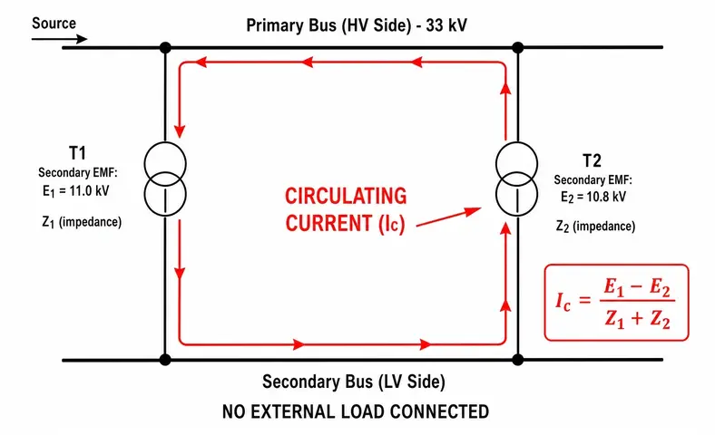
The circulating current is driven by the voltage difference between the secondary voltages of the two transformers. The formula for circulating current is:
\(I_c=\dfrac{\Delta E}{Z_1+Z_2}\)
Where:
- \(I_C\) = Circulating current
- \(\Delta E\) = Difference in secondary EMF (voltage difference)
- \(Z_1\) = Impedance of Transformer 1 (referred to secondary)
- \(Z_2\) = Impedance of Transformer 2 (referred to secondary)
5.1 Numerical Example:
T1: 11 kV / 415 V, 1000 kVA, Z1 = 0.02 Ω
T2: 11 kV / 420 V, 1000 kVA, Z2 = 0.025 Ω
\(\Delta E = 420 − 415 = 5 \text{ V}\)
\(I_C = \dfrac{5}{0.02+0.025}\)
\(I_C = \dfrac{5}{0.045}\)
\(I_C = 111.1 \text{ A}\)
This 111.1 A flows between the two transformers without doing any useful work. At 1000 kVA and 415 V, the rated secondary current is approximately 1390 A. So a circulating current of 111 A is about 8% of rated current which is enough to cause heating and reduce available load capacity.
6. Load Sharing in Parallel Transformers
Load sharing refers to how the total load current is distributed among the parallel-connected transformers. Correct load sharing is one of the main goals of parallel operation.
The load shared by each transformer depends on its kVA rating and its per-unit impedance. In an ideal case where both transformers have the same voltage ratio and same per-unit impedance, the load is shared in proportion to their kVA ratings.
6.1 Case 1 — Same kVA Rating and Same Impedance
This is the simplest case. If T1 and T2 both have the same kVA rating and the same per-unit impedance, they share the load equally.
Example:
T1 = 1000 kVA, 5% impedance
T2 = 1000 kVA, 5% impedance
Total Load = 1800 kVA
Load on T1 = 1000 / 2000 × 1800 = 900 kVA
Load on T2 = 1000 / 2000 × 1800 = 900 kVA
Both transformers operate at 90% of their rated capacity. This is a good and balanced arrangement.
6.2 Case 2 — Different kVA Ratings but Same Per-Unit Impedance
If both transformers have the same per-unit impedance but different ratings, they share the load in proportion to their kVA ratings.
Example:
T1 = 1000 kVA, 5% impedance
T2 = 500 kVA, 5% impedance
Total Load = 1200 kVA
\(\text{Load on T1} = \dfrac{S1}{S1 + S2} \times \text{Total Load}\)
\(\text{Load on T1} = \dfrac{1000}{1500} \times 1200 = 800 \text{kVA}\)
\(\text{Load on T2} = \dfrac{500}{1500} \times 1200 = 400 \text{kVA}\)
T1 carries 80% of its rating. T2 also carries 80% of its rating. Load sharing is proportional and fair.
6.3 Case 3 — Different kVA Ratings and Different Per-Unit Impedances
This is the most common real-world situation. The load shared by each transformer is inversely proportional to its per-unit impedance and proportional to its kVA rating.
The formula used is:
\(\text{Load on T1 (kVA)} = \dfrac{Z_2}{Z_1+Z_2}\times \text{Total Load}\)
\(\text{Load on T2 (kVA)} = \dfrac{Z_1}{Z_1+Z_2}\times \text{Total Load}\)
Here Z1 and Z2 are the per-unit impedances normalized to the same base kVA. This is an important step many engineers miss in practice.
Normalizing Per-Unit Impedance to a Common Base:
\(Z_{new} = Z_{old} \times \dfrac{{kVA}_{base}}{{kVA}_{transformer}}\)
Numerical Example:
T1 = 1000 kVA, Z1 = 5%
T2 = 500 kVA, Z2 = 4%
Total Load = 1200 kVA
Common Base = 1000 kVA
Normalize T2 impedance to 1000 kVA base:
\(Z_{2-new} = 4\% \times \dfrac{1000}{500} = 8\%\)
Now calculate load sharing:
\(\text{Load on T1} = \dfrac{Z_{2-new}}{Z_1+Z_{2_new}}\times \text{Total Load}\)
\(\text{Load on T1} = \dfrac{8}{5+8}\times 1200 = 738.5 \text{ kVA}\)
\(\text{Load on T2} = \dfrac{Z_1}{Z_1+Z_{2-new}}\times \text{Total Load}\)
\(\text{Load on T2} = \dfrac{5}{5+8}\times 1200 = 461.5 \text{ kVA}\)
Check: T1 is at 738.5 / 1000 = 73.85% loading. T2 is at 461.5 / 500 = 92.3% loading. T2 is more heavily loaded despite its smaller size. This happens because T2 has a lower impedance, which causes it to draw more current.
This example shows why matching per-unit impedances is important. In this case, T2 might be overloaded at peak demand.
7. Effect of Unequal Transformer Ratings on Parallel Operation
In practice, it is not always possible to get two transformers of exactly the same rating for parallel operation. Engineers sometimes must work with what is available. The accepted practice is to allow a ratio of no more than 2:1 between the kVA ratings of two parallel transformers.
For example, a 1000 kVA transformer can work in parallel with a 500 kVA transformer. But connecting a 1000 kVA transformer in parallel with a 100 kVA transformer would not be practical because the smaller unit would be severely overloaded or the larger unit would be significantly underutilized.
Also, the percentage impedance must be close enough that neither transformer gets overloaded. Industry practice suggests keeping the impedance ratio within the range of 0.9 to 1.1 when normalized to the same base.
8. Protection for Parallel Transformer Operation
When transformers are operated in parallel, protection requirements change compared to a single transformer installation. Each transformer needs its own protection, and the parallel arrangement introduces additional protection challenges.
8.1 Differential Protection (ANSI 87T)
Each transformer should be equipped with a differential protection relay. The differential relay compares the current entering and leaving the transformer. If there is a difference beyond a set threshold, the relay trips the transformer. In parallel operation, the CT (current transformer) connections must be carefully arranged so that the circulating current between parallel units does not cause false trips.
8.2 Overcurrent Protection (ANSI 51)
Each transformer should have overcurrent protection on the primary and secondary sides. The overcurrent relay settings must account for the fact that fault current can come from multiple parallel transformers.
ANSI Device Number:
51 = Time Overcurrent Relay
50 = Instantaneous Overcurrent Relay
8.3 Reverse Power / Circulating Current Protection
In some parallel transformer configurations, especially when one transformer develops a fault or starts to operate incorrectly, circulating currents can flow between the units. Monitoring the circulating current and alarming or tripping when it exceeds a safe level is a good engineering practice.
8.4 Buchholz Relay (ANSI 63)
For oil-filled transformers, the Buchholz relay detects internal faults by detecting gas accumulation or oil surge inside the transformer tank. Each parallel transformer should have its own Buchholz relay.
8.5 Transformer Neutral Grounding
For parallel wye-connected transformers, the neutral grounding arrangement must be carefully managed. If both transformers have solidly grounded neutrals, zero-sequence current can circulate between them during unbalanced fault conditions. Engineers sometimes use neutral grounding resistors or reactors to limit zero-sequence circulating currents.
9. Practical Example: Parallel Transformer Operation in a Distribution Substation
Let us look at a real-world scenario. A distribution substation serves an industrial park in a manufacturing zone. The original design had one 2500 kVA, 11 kV / 415 V, Dyn11 transformer with 5.75% impedance (T1). Over three years, the load grew to 3800 kVA during peak production hours.
The utility and facility engineers decided to add a second transformer (T2) in parallel. T2 was specified as 2000 kVA, 11 kV / 415 V, Dyn11 with 5.5% impedance.
Step 1: Check Conditions
- Voltage ratio: Both are 11 kV / 415 V. Condition satisfied.
- Vector group: Both are Dyn11. Condition satisfied.
- Phase sequence: Verified using a phase sequence meter. Both are A-B-C. Condition satisfied.
- Polarity: H1-H2-H3 and X1-X2-X3 terminals matched correctly. Condition satisfied.
- Per-unit impedance: T1 = 5.75%, T2 = 5.5%. Ratio = 5.75/5.5 = 1.045. Within the acceptable range of 0.9 to 1.1. Condition acceptably satisfied.
Step 2: Calculate Load Sharing at 3800 kVA
Normalize impedances to a common base of 2500 kVA:
\(Z_{1-new} = 5.75\%\) (T1 is already at 2500 kVA base)
\(Z_{2-new} = 5.5\% \times \dfrac{2500}{2000} = 6.875\%\)
Load on T1:
\(S_{T1} = \dfrac{Z_{2-new}}{Z_{1-new} + Z_{2-new}} \times \text{Total Load}\)
\(S_{T1} = \dfrac{6.875}{5.75+6.875}\times 3800 = 2069.5 \text{ kVA}\)
Load on T2:
\(S_{T2} = \dfrac{Z_{1-new}}{Z_{1-new} + Z_{2-new}} \times \text{Total Load}\)
\(S_{T2} = \dfrac{5.75}{5.75+6.875}\times 3800 = 1730.5 \text{ kVA}\)
Step 3: Check Loading Percentages
T1 loading: 2069.5 / 2500 = 82.8% — acceptable.
T2 loading: 1730.5 / 2000 = 86.5% — acceptable.
Both transformers are within safe operating limits. The parallel arrangement successfully handles the 3800 kVA load without overloading either unit.
10. Synchronization and Switching Procedure for Parallel Operation
Before connecting a second transformer in parallel with a running transformer, the following procedure is followed in practice:
Step 1: Verify that the incoming transformer (T2) is de-energized.
Step 2: Check all physical connections: primary terminals H1-H1, H2-H2, H3-H3 and secondary terminals X1-X1, X2-X2, X3-X3 are correctly matched.
Step 3: Energize T2 on the primary side by closing the primary breaker or switch. Allow T2 to build up its secondary voltage.
Step 4: Use a synchronizing voltmeter or synchroscope to compare the secondary voltage of T2 with the existing bus voltage (from T1). The voltages must be equal in magnitude and phase angle before closing the secondary breaker.
Step 5: Close the secondary breaker of T2. T2 is now in parallel with T1.
Step 6: Monitor current distribution on both transformers using ammeters or a SCADA system.
11. Conclusion
Transformer parallel operation is a well-established and widely used engineering technique in power systems. It provides increased capacity, better reliability, and greater operational flexibility.
The five conditions — matching voltage ratio, polarity, per-unit impedance, phase sequence, and vector group must all be satisfied. Skipping any one of them leads to circulating currents, unequal load sharing, or worse, transformer damage.
12. Frequently Asked Questions (FAQs)
All five conditions — same voltage ratio, same polarity, same per-unit impedance, same phase sequence, and same vector group — are important. However, from a safety perspective, the phase sequence and vector group conditions are the most immediately damaging if violated.
Yes, transformers with different kVA ratings can be operated in parallel. The key requirement is that their per-unit impedances (normalized to the same base) should be close to each other — ideally within a ratio of 0.9 to 1.1.
If the percentage impedances are significantly different, the load sharing will be unequal. The transformer with lower impedance will carry more than its proportional share of the load.
For single-phase transformers, polarity can be checked using the voltage test method. For three-phase transformers, the vector group and terminal markings (H1, H2, H3, X1, X2, X3) are checked against the nameplate and verified by a phase angle measurement.
Adding a second transformer in parallel reduces the total source impedance as seen from the load bus. This increases the available short-circuit current at the bus.
Yes, three or more transformers can be operated in parallel. The same five conditions apply to all units.